Introduction
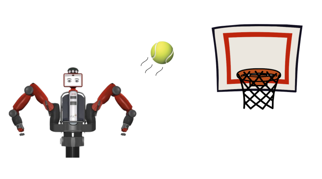
This project programs a Baxter robot (Rethink Robotics) to pick up a tennis ball from a table and throw it into a bin. The ball and the bin are both detected using single camera computer vision.
Making a robot throw an object is a harder task than it seems. It involves sensing to a high degree of precision in order to guarantee consistency. It also requires complicated path planning to enable the Baxter to throw at a large range of distances. Building a ball throwing robot could be useful for training baseball players or for automating the process of sorting items into bins in a factory.
Design
1. Overall
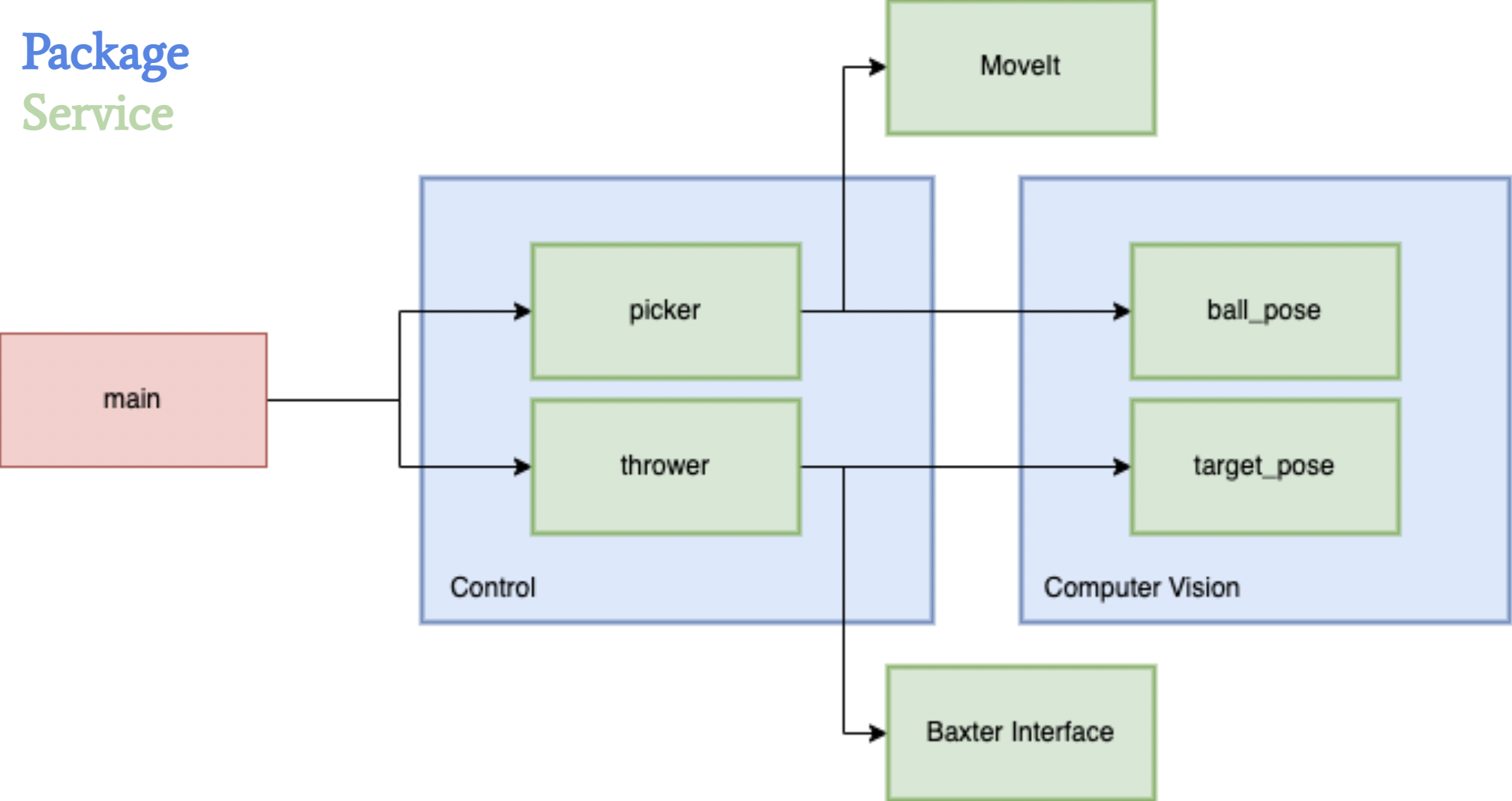
For the overall architecture of the system, we wanted to separate the nodes in such a way that it would be easy to work in parallel with minimal dependencies on independent parts of the codebase. This would allow us to mock data from various services without being blocked on completion of any one part of the project.
2. Picker
For the Baxter to throw the ball, we must first be able to locate and pick up the ball consistently. Because the ball is a spherical object, we needed to be able to localize the ball very precisely such that the gripper is placed along the diameter of the ball. To locate the ball, we first position the throwing arm at an initial pose, such that the arm’s camera is facing down at the table. Using images taken by the camera, we detect the location of the ball within the image using image segmentation code. We then translate the ball’s 2D coordinates within the image to its 3D pose in the world. We then move the arm to the provided pose in order to pick up the ball. While this approach produced desired results, one of the major trade-offs we faced when experimenting with the design were the restrictions on where we could pick up the ball from, as the ball had to be located within the camera frame of the initial pose. We initially wanted to use a two camera approach with both of the arm cameras for depth estimation, which would allow us to do a sweep of our surroundings when locating the ball. However, we realized that it was a very difficult task to get this approach to produce consistent and precise 3D poses, and that the margin of error was too great. While the robustness of a two camera approach would be ideal for real world scenarios where we don’t want to restrict the area in which the Baxter can locate the ball, we ended up valuing precision more with our final design.
3. Thrower
When designing the throwing component of the code, one of the key considerations was to enable the Baxter to throw a large range of distances. Furthermore, we wanted the throws to be consistent such that the only errors we would have to worry about were not mechanical. Finally, the last important requirement of the design was to be able to throw in multiple directions. After experimenting with end-effector space vs. joint space control and various designed trajectories (overhand, underhand, sideways, various combinations of joints), we decided to restrict the movement of the Baxter arm to 3 joints: the shoulder, the elbow, and the wrist. Then, we would control the velocity of the joints and the release angle to obtain a target distance based on where the bin was located. The shoulder would be used to control the direction that the ball is being thrown in. Although we were able to guarantee a consistent throw by only using three joints, one of the major trade-offs of using fewer joints is that we have lower torque and, as a result, a smaller throwing range. In a real world situation such as building a robot to train baseball players, having such a tradeoff may not be acceptable because this task requires both speed and distance.
Implementation
1. Picker
In our picker control loop, we always start by moving Baxter’s arm to an initial position above the table, where the arm camera faces directly downwards at the table. Given a service request to pick up the ball, we locate the ball in the resulting image frame, translate its 2D coordinates to its 3D pose, and then move the end effector of the arm to that resulting location to grip the ball.
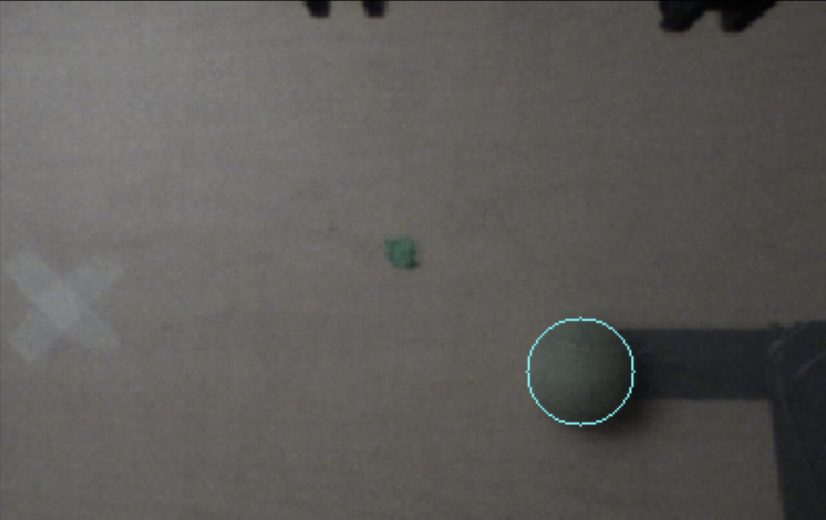
To locate the tennis ball on the table, we first subscribe to the image topic corresponding to the throwing arm’s camera. We run our ball detection algorithm on incoming frames until a ball is located within the frame, making sure to skip any frames that come in while the algorithm is running. Since the tennis ball is green, our ball detection algorithm uses HSV thresholding to segment green pixel clusters within the image. Once the thresholding produces detected clusters of green pixels, we erode and dilate the clusters to remove artifacts while preserving the general shape of the ball. After generating contours using these clusters, we pick the contour with the largest area to represent our ball and find the minimum enclosing circle that contains all points within the cluster. This provides us with a 2D pixel coordinate that represents the center of the ball within the image frame.
Given the location of the center of the ball in respect to the image frame, we want to translate the 2D image coordinates into corresponding 3D world coordinates. Luckily, since we detect the image from a predetermined initial location above the table, we can naively set the Z position of the ball pose to the height of the table. By taking an image of a grid pattern from that initial position, we are also able to determine the meter per pixel translation along each of the X and Y axes. This provides us with a linear mapping of 2D image coordinates to 3D world coordinates, as long as we make sure to set the camera resolution to 640 x 400 during the initial calibration of the Baxter. We also make sure to add a small offset in the X and Y positions of the pose to account for the distance discrepancy between the center of the camera lens and the center of the grippers.
Once the picker receives a 3D ball pose from the processes outlined above, it is able to direct the end effector to the specified location using the MoveIt controller. We first take aim by moving the end effector ~0.2 meters above the ball to make sure that the end effector points downwards when grabbing the ball. The end effector then moves to the desired position and securely grips the ball. Once the ball is located within the Baxter’s gripper, we can proceed with throwing the ball into the bin.
2. Thrower
The thrower program manages ROS services, initialization of gripper and arm motors, etc. Given a service request to throw (containing vision's detected bin pose), we calculate the appropriate shoulder angle, wrist and elbow velocities, and release point by interpolating between experimentally measured ball landing poses given various input parameters. We can choose either a multi-joint throw or single-joint throw for shorter distances, and then execute the throw maneuver.
The arm configures into an initial position in which the wrist and elbow axes of rotation are parallel to each other and perpendicular to the shoulder joint. We then take aim by aligning the shoulder to maneuver the end effector's reachable workspace to be coplanar with the target bin, and winding up the wrist and elbow away from the target to make space to accelerate. Then, we execute the throw by setting the wrist and elbow rotational velocities to a calculated value in a loop. During this loop, we measure the joints' angles, and as soon they exceed a computed threshold we release the ball. We also use the joint angles to stop the robot if we determine the trajectory has ended or the joints have exceeded our safety restrictions.
3. Camera calibration
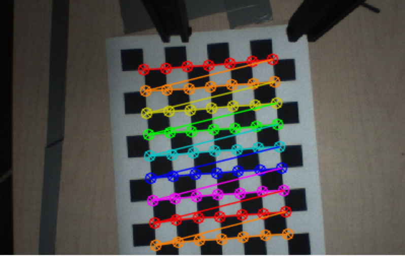
Using a printed checkerboard pattern, we use OpenCV's methods to identify corners in the image to subpixel precision. We label the object coordinates of each corner in the chessboard's frame, with origin at the top left intersection of tiles, axes aligned to the tiling, and units equal to a tile's side length. Using the correspondence between image coordinates and object coordinates, we estimate the camera's intrinsic matrix for undistortion. The intrinsic parameters from calibration are saved in a file that is accessed in the node initialization of our ROS system.
Further, we are able to use the computed rotation and translation vectors encoding the twist between the camera and object frame to compute a projection from a homogenous image coordinate to the checkerboard plane in the object's coordinate frame (Z=0). By calibrating to a photo of the checkerboard on the table, scaling the object axes by the checkerboard side-lengths, then rotating and translating to the robot base frame, we are able to take a pixel to a checkerboard coordinate to a pose on the table in the robot's frame!
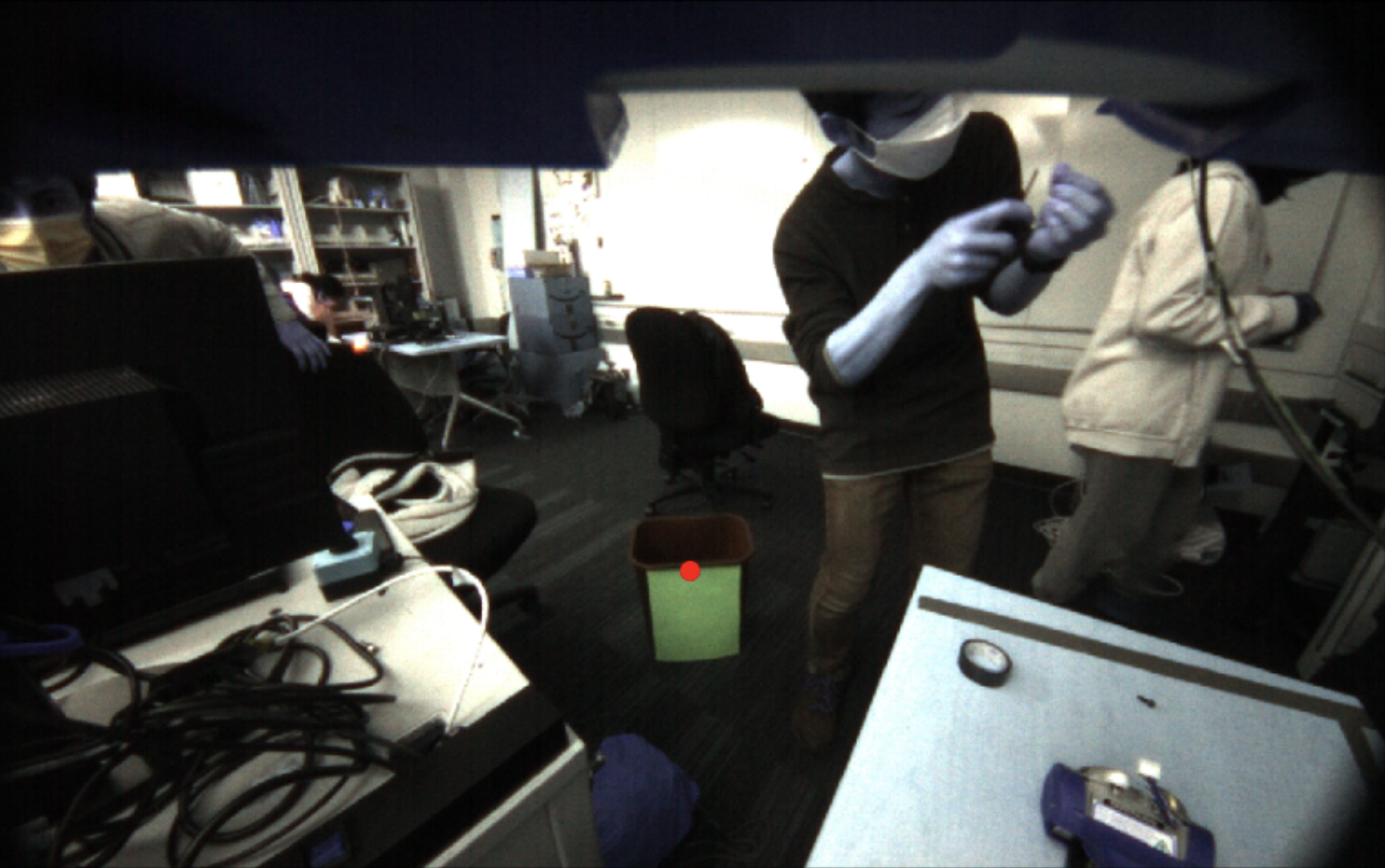
Using this transformation, we can use trigonometry to map between pixel values and angles away from the camera's heading. This is calculated from the ratio of the known height of the camera off the table and the translation along the table computed from the object plane projection. Thus the table pose calibration is able to be reused for bin localization, even though the camera moves and the checkerboard plane is no longer relevant. By finding a ray (in homogeneous coordinates in the camera frame) from the camera to the bin, we can find its intersection with the plane in robot coordinates with Z=h – the known height of the bin – to get the bin's pose in robot coordinates.
Results
We were able to program the Baxter to localize a bin and a ball with reasonable accuracy. We were also successful in building a fully integrated system that can take the localization data and convert that into arm movements to pick up and throw the ball. The Baxter was able to throw the ball anywhere within a range of 35-65in, with under 1in precision for repeated trajectories.
(the AR tag and gripper modifications are not from our project)
Conclusion
Overall, we were able to achieve most of the initial goals we set for ourselves. We incorporate all three of sensing, planning, and actuation, and our robot is able to localize the ball, pick up the ball, localize the target, and throw the ball to the target. However, we were unable to make it work as consistently as we had initially hoped - we occasionally had issues accurately picking up the tennis ball or throwing the ball the right distance.
Picking up the ball with the Baxter grippers presented an interesting challenge, as small offsets in the positioning would make the ball move off to the side and prevent a successful pickup. Another difficulty we had was combining the MoveIt controller with a joint state controller. When we tried to control joint states directly after using MoveIt, we found that the robot would continuously try to stay at the same spot, leaving the robot locked in position. We eventually were able to work around this by separating the nodes and killing one before we started the next.
Overall, our solution is robust but does have some slight flaws. For picking up the ball, we rely on having a fixed location for the camera and also on precise camera calibration for the individual robot. This camera calibration is also required for target localization but is not a significant flaw because the calibration procedure is simple and quick to perform. Another minimal flaw is our limited range. We are only able to throw a distance of 65in, which limits the range of locations where our target can be placed. However, this was a result of Baxter's internal limitations on joint angles and joint velocities, not our code.
Given additional time, we would like to further improve the consistency of our system and look into ways to extend the range of throwing.